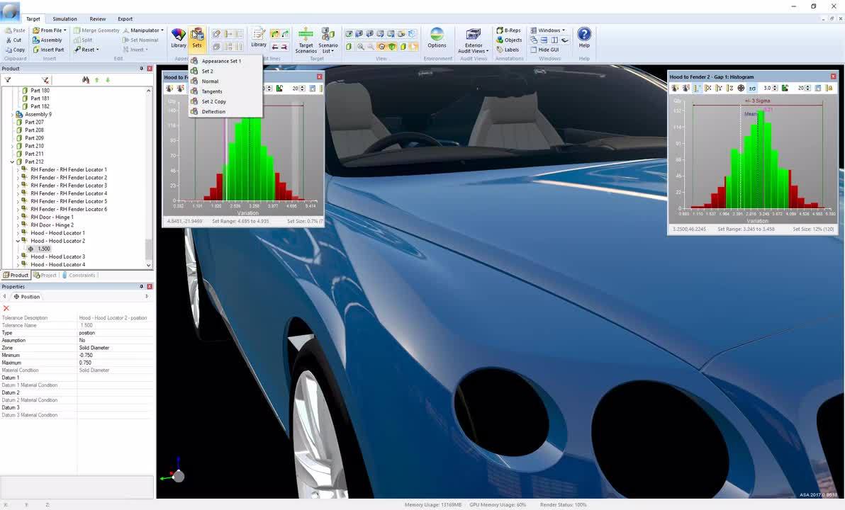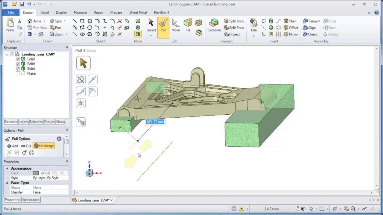

Convert it into a mesh and the result will be a deformed mesh. This will impact subsequent steps and the accuracy of results.īy contrast, the new tools in Ansys R17 automatically monitor deformation and remesh the part at appropriate intervals, so that results remain consistent as the part deforms.Īlso related to working with deformed geometry, there are tools that make it easier to take the geometry from one simulation and feed it back into another process.įor example, when you’re simulating the stamping process, you’ll start with clean, analytic geometry. Issues then arise because of the large-scale deformation of that component in other words, the shape changes (and changes dramatically in many cases), so that the original mesh isn’t suitable for subsequent time steps in the study. When a study is set up, the typical workflow sees the undeformed component used as the basis for the mesh. Many of the problems here come down to the meshing of geometry.
ANSYS SOFTWARE MANUAL
The adaptive meshing for large deformations lets you get closer to an accurate result, without the need for intermediate steps and manual adjustment Ansys R17 – Handling deformationĪnother focal point for Ansys R17 is the process of simulating large-scale deformation of parts – specifically, within non-linear simulations. It can also become part of a larger system of simulations. But it can, of course, also be dialled up, so that a higher resolution mesh is generated.Įither way, the mesh can then be used for a number of purposes, and can give you a more realistic view of how heat affects components and those around them.

The system then generates a mesh that allows it to represent each of the different materials in its elements.Īs you can see from the image below, this can be a low-resolution mesh with quite coarse replication of those details. The trace is then imported from a system like Mentor and the trace information is mapped onto the mesh in the FEA model. You then define each layer – substrate, copper and so on. These are typically pretty standard and the same process can be applied to a flexible PCB just as easily as a rigid one. You begin with modelling the board itself. With this release, the setup work done can be done in a few clicks. The new tools make the process much easier - and PCBs can be tricky, because of the need to simulate the board itself, with its multi-layered construction, the traces that provide the circuitry and the components assembled onto the board. Ansys R17 – PCB simulationĪ big area of focus for Ansys Workbench R17 is in increased automation when it comes to setting up jobs that heavily feature PCB data. That allows you to combine results of different physics models in a way that previously would have been complex, time-consuming and error-prone. You simply drag a connector from the output of one process (for example, a thermal study) onto another (say, the loading conditions of a stress analysis) and the system handles the rest. Much of the company’s work here centres on the Workbench platform, with its graphically-led (as opposed to command line driven) interface that guides users through a dynamic process of simulation set-up, linking together the constituent parts of a study.įor run-of-the-mill tasks, this may not offer big benefits (beyond making the setup process clearer), but for more complex tasks, its strengths soon become apparent.Īs multi-physics studies increasingly become the norm, Workbench is built to allow inputs or outputs from one study to be fed into another. It’s no surprise, then, that Ansys has been working to consolidate and centralise its core application set.

And, at the same time, the company has built up a wide range of more special-purpose code, allowing users to simulate electromagnetic fields, for example, or cold flow in internal combustion engines. There have been big acquisitions involving CFD technologies, such as the takeovers of CFX in 2003 and Fluent in 2006.

ANSYS SOFTWARE SOFTWARE
And while the company’s reputation was undoubtedly built on its structural analysis capabilities, the last decade or so has seen Ansys – and its software portfolio – expand considerably. It continues to be a market leader it’s even considered to be the de facto standard for simulation at many organisations. Ansys R17 lets you take PCB data from a variety of formats, extract where the traces would lie, map them to a mesh and simulate them in a much shorter timeframe


 0 kommentar(er)
